русский
 عربى
عربى


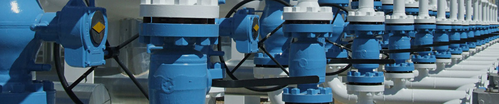
A pipeline needs more than one type of valve to respond to genuinely different operating needs throughout its run. A ball valve controls whether fluid moves through a section of the line, while a relief valve provides a completely separate response when pressure conditions call for attention. When these functions get planned together from the start, operators can manage normal flow without ever confusing flow control with pressure protection, which is exactly the kind of mix-up that leads to a bad afternoon on site.
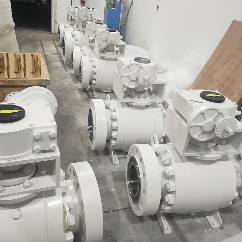
This distinction matters across industrial pipelines, water systems, air systems, and plenty of other fluid-handling applications running quietly in the background of daily operations. The valve used for routine opening and closing serves a genuinely different purpose from the device intended to release pressure when things go sideways. Understanding this relationship helps engineers, installers, and equipment buyers make more practical decisions when configuring a pipeline from the ground up.
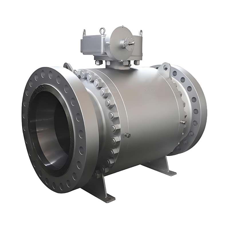
Ball valves get used commonly when a pipeline needs a clear, unambiguous open or closed flow path, nothing fancier than that. Their operating role stays fairly straightforward, which makes them suitable for isolating sections of a system or simply controlling whether fluid can pass through a particular point at all.
A relief valve responds to a genuinely different requirement altogether. Instead of controlling everyday flow according to an operator's schedule or preference, it exists to provide a pressure-release path once the system reaches a condition that actually calls for pressure to get relieved. The two valve types can therefore sit in the same pipeline without ever performing the same job.
| Valve Type | Main Role | Typical Pipeline Purpose |
|---|---|---|
| Ball valve | Opening and closing | Isolating or controlling a flow path |
| Relief valve | Pressure release | Providing a response to excessive pressure |
| Check valve | Flow direction | Helping prevent unwanted reverse flow |
| Control valve | Flow adjustment | Managing flow according to system needs |
This functional separation makes pipeline operation a lot easier to understand at a glance, even for someone new walking the plant floor. The ball valve manages the normal flow path day to day, while the relief valve stays part of the system's pressure protection arrangement quietly waiting in the background.
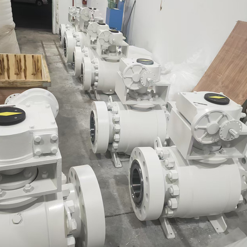
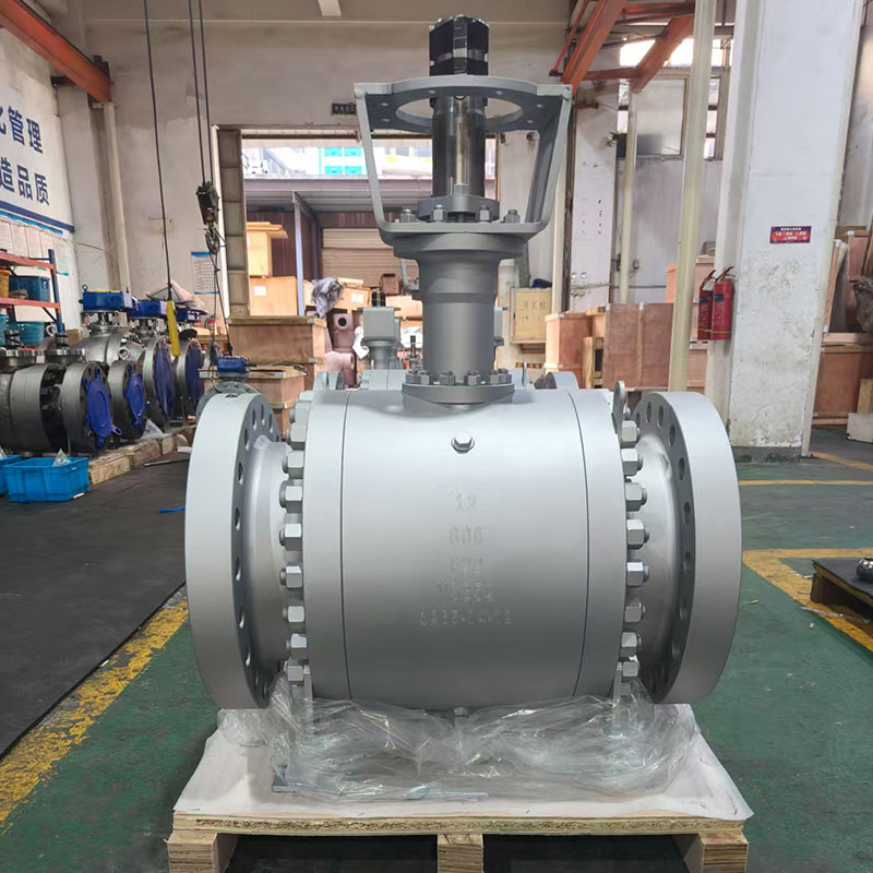
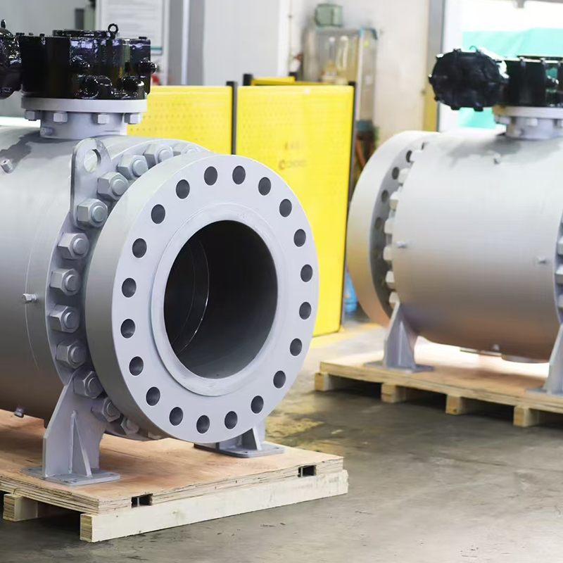
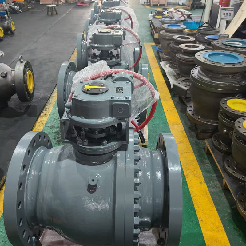
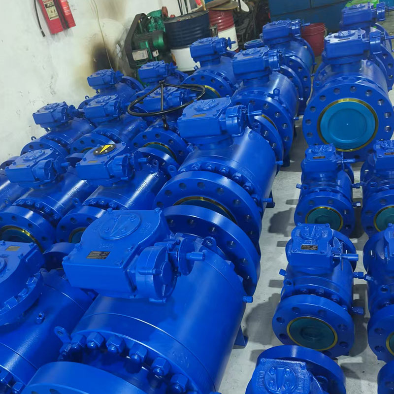
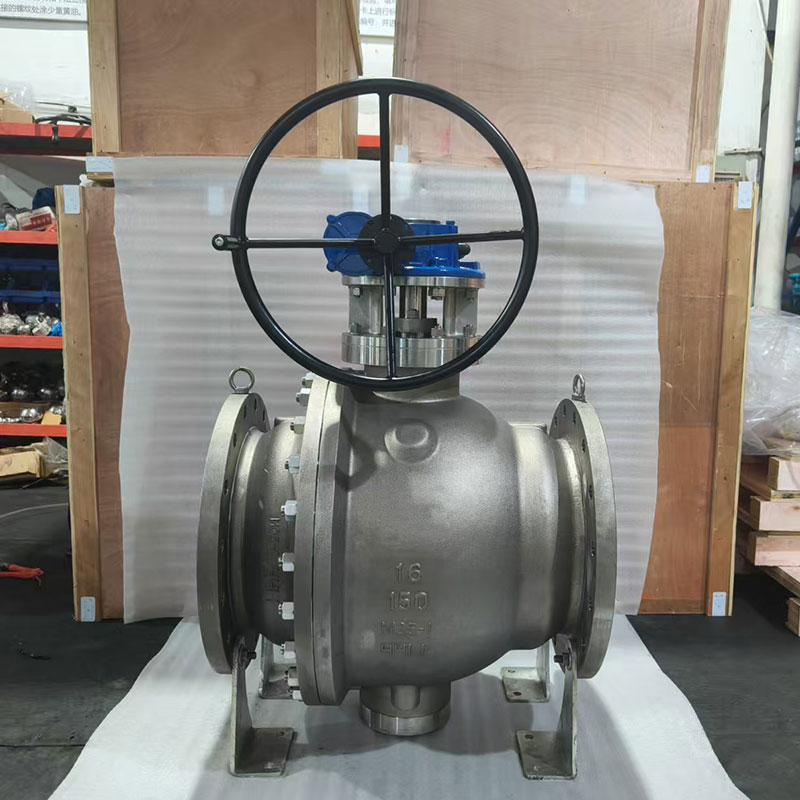
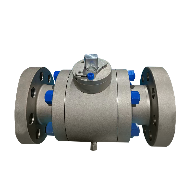
A Corrosion Resistant Ball Valve proves useful wherever the valve gets exposed to conditions that would otherwise chew through ordinary materials over time. Its role stays focused on opening and closing the pipeline just like any other ball valve, but material selection shapes how the valve actually performs across long-term service without needing replacement every year.
The valve often gets installed at points where operators need to isolate equipment, stop flow during maintenance, or separate one section of a pipeline from another entirely. This makes accessibility and operating convenience genuinely important parts of valve selection, not just an afterthought once the pipe's already welded in place.
A practical installation might place a ball valve near equipment that requires periodic inspection, like a pump or filter housing. Closing the valve separates that section from the rest of the system, letting maintenance work happen without treating the entire pipeline as one continuous flow path that has to shut down completely.
The corrosion-resistant design doesn't change the basic purpose of the valve one bit. It simply supports the valve's intended service conditions while the opening and closing function stays central to how it actually gets used day after day.
Material compatibility deserves consideration during selection too, not just a glance at the price tag. The fluid, surrounding environment, connection arrangement, and expected maintenance routine all shape whether a particular valve construction genuinely suits the application it's headed for.
An Air Safety Relief Valve ties to pressure management rather than routine pipeline isolation, and that distinction matters more than it might seem at first glance. Its purpose is providing a controlled way for air or gas pressure to get released once the system reaches a condition that genuinely requires relief.
This proves useful in systems where pressure can shift during operation, sometimes gradually and sometimes fast. The relief valve stays inactive during ordinary conditions when pressure sits comfortably within the intended operating range, but it provides a separate release path the moment pressure conditions move beyond that expected operating state.
The distinction from a ball valve matters quite a bit here. A ball valve normally responds to an operator's action or a written operating procedure, while a safety relief valve responds to pressure conditions themselves, without anyone needing to touch it.
| Operating Need | Ball Valve | Air Safety Relief Valve |
|---|---|---|
| Start or stop flow | Suitable | Not its primary role |
| Isolate equipment | Suitable | Not its primary role |
| Routine flow path control | Suitable | Not its primary role |
| Pressure release | Not its primary role | Suitable |
| Pressure protection | Limited to isolation function | Designed for this purpose |
A pipeline often needs both types of valves working alongside each other. One manages the normal flow route day to day, while the other stands ready to provide a pressure-related safety function whenever it's actually needed.
A Pneumatic Safety Relief Valve gets considered when a pipeline forms part of a system running on compressed air or pneumatic equipment, the kind found throughout manufacturing floors and packaging lines. Its application depends heavily on the pressure conditions involved and how the complete system gets arranged around it.
Pneumatic systems often include multiple components working together in sequence. Air supply equipment, pipelines, valves, actuators, and connected machinery all influence how pressure actually behaves throughout the day. A safety relief device provides a dedicated part of the system specifically for handling pressure-release needs when they arise.
The presence of automation doesn't remove the need for clear functional separation between components. Automated equipment still needs defined methods for flow isolation and pressure protection, robots and sensors notwithstanding.
A ball valve might get used to isolate a pneumatic section during maintenance or operational changes on the line. The pneumatic relief valve serves its separate pressure-related function the whole time, without ever getting treated as some substitute for the ball valve doing a completely different job.
This arrangement also makes maintenance procedures a lot easier to organize for whoever's running the shift. Operators can identify at a glance which component is intended for isolation and which one is tied to pressure relief instead.
Positioning depends heavily on the purpose of the pipeline and the equipment connected to it along the way. There's no single arrangement that suits every installation out there, so valve placement should get based on the actual flow path, pressure conditions, maintenance needs, and system layout in front of the engineer.
A ball valve often gets placed wherever isolation proves useful in practice. Equipment might need separating from the main pipeline during inspection, cleaning, or replacement work, and the valve provides a practical way to interrupt that section of the flow path without shutting down everything else.
A relief valve needs positioning where it can actually respond to the pressure condition it's meant to address, not just wherever there happened to be room on the pipe. Its location should get considered as part of the pressure protection arrangement, rather than simply placed beside another valve out of convenience.
A simplified pipeline layout might include:
Fluid source → Ball valve → Equipment section → Relief valve → Downstream pipeline
The actual arrangement can differ quite a bit depending on the system in question. The important principle stays that each valve should have a clearly defined role and should sit positioned so its intended function never gets blocked or compromised by some other component crowding it out.
Accessibility matters here too, more than people sometimes plan for. Operators should be able to inspect and maintain the valves without creating unnecessary disruption to the rest of the pipeline running nearby.
Yes, quite noticeably in fact. Valve selection shapes how easily a pipeline can get inspected, isolated, and serviced over its working life. A system with clearly assigned valve functions tends to be a lot easier for maintenance personnel to understand, especially someone new to that particular plant.
A ball valve provides a convenient isolation point when needed. When a section of pipe or connected equipment needs attention, operators can use the valve according to the system's operating procedure rather than disturbing unrelated sections that were working just fine.
Relief valves call for a different maintenance approach entirely. Their pressure-related function means inspection should consider whether the valve remains suitable for its intended protective role, not just whether it opens and closes smoothly.
Maintenance teams can review several practical areas during a routine check:
The maintenance plan should distinguish clearly between routine flow-control components and pressure-protection components. Treating every valve the same way makes it a lot harder to figure out whether a problem actually involves flow isolation or pressure relief once something starts acting up.
Clear labeling and documentation help quite a bit here too. When a pipeline contains several valve types side by side, personnel should be able to understand the purpose of each component without relying purely on its appearance or guessing from memory.
Buyers should consider the entire pipeline rather than selecting valves as isolated products picked off a catalog page one at a time. The fluid being handled, environmental conditions, operating requirements, maintenance practices, and equipment connections all shape what configuration actually makes sense for the job at hand.
For a Corrosion Resistant Ball Valve, material compatibility and operating conditions deserve real attention, since the valve will perform a routine flow-control role day in and day out. The buyer should also consider how frequently the valve will actually get operated and whether the installation requires regular isolation as part of normal work.
For an Air Safety Relief Valve or Pneumatic Safety Relief Valve, the pressure-management role climbs to the top of the priority list instead. The relief device should correspond with the intended system conditions and should sit in a suitable installation position that lets its protective function operate exactly as intended when the moment calls for it.
| Selection Question | Ball Valve Consideration | Relief Valve Consideration |
|---|---|---|
| What does the component control? | Flow path | Pressure condition |
| Is isolation required? | Yes, where needed | Not its main purpose |
| What environment is involved? | Material compatibility | Material and service compatibility |
| What maintenance is expected? | Operation and inspection | Inspection and pressure-related checks |
| Where should it be installed? | At a useful isolation point | At a suitable pressure protection point |
This approach helps buyers dodge a common mistake seen on plenty of job sites: expecting one valve to somehow perform every function at once. Flow control and pressure relief both relate to pipeline operation, sure, but they call for genuinely different responses when things actually happen.
Functional separation gives each valve a clear job to do, without any overlap muddying the picture. The ball valve handles normal opening and closing throughout the day, while the relief valve addresses pressure conditions that require a release path when they arise. This makes the pipeline a lot easier to plan, since the purpose of each component can get considered on its own terms.
The relationship becomes especially useful once a pipeline contains several pieces of equipment strung along its length. Operators may need to isolate one section without changing the pressure protection arrangement for another part of the system entirely, and clear separation makes that possible without a headache.
A well-planned system can therefore combine a Corrosion Resistant Ball Valve with an Air Safety Relief Valve or Pneumatic Safety Relief Valve, provided the selected components genuinely suit the application and get installed according to the actual system design rather than guesswork.
The same principle carries through during maintenance too. A ball valve helps isolate a section when needed, while the relief valve stays associated with its pressure-management role the whole time. Keeping these functions distinct helps operators understand exactly what each valve is expected to do without second-guessing.
When pipeline designers look at valves as parts of one coordinated system, rather than a pile of individual components picked separately, decisions about placement, maintenance, accessibility, and operating procedures become a lot easier to organize from day one. The result is a pipeline where routine flow control and pressure protection carry separate but genuinely complementary roles, each doing its own job well.