русский
 عربى



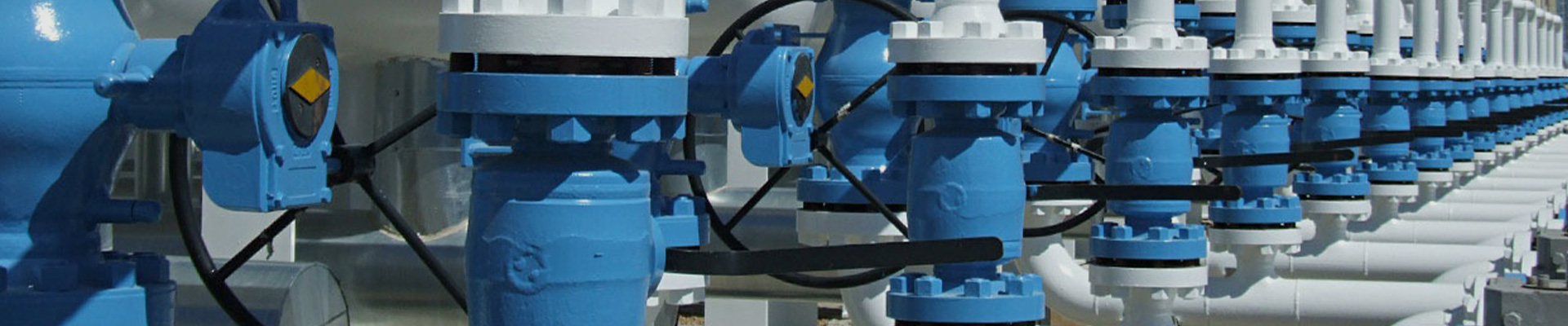
A boiler at a food plant, a compressor tank in a workshop, and a reactor in a chemical complex all share one risk: pressure that climbs faster than anyone expected. A blocked outlet, a failed controller, or a fire near a vessel can push pressure past what the walls can handle. An Industrial Safety Valve is the device that opens on its own and lets the excess escape before equipment is damaged. Below is how these valves work, which types exist, and what to check before ordering.
An Industrial Safety Valve protects pressurized equipment and piping from exceeding allowable limits. It needs no operator, no power supply, and no signal. When pressure reaches the set pressure, the valve opens and discharges fluid. When pressure falls back to the reseating pressure, it closes again.
You will find these valves in many places:
The two names are often swapped in daily conversation, but they describe different behavior. A safety valve is traditionally linked with gas and steam, where a quick, full opening is needed. A relief valve is traditionally linked with liquids, where the opening grows gradually as pressure rises.
A safety relief valve combines traits of both. Standards and manufacturers define these terms slightly differently, so check the wording in the project specification rather than relying on the name alone.
The right design depends on the fluid, the discharge system, and how much the outlet pressure can vary.
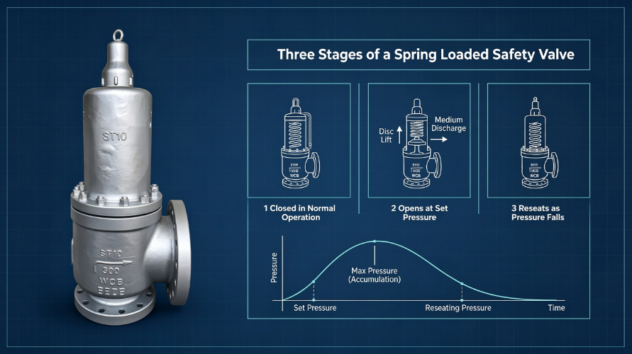
A Spring Loaded Safety Valve uses a compressed spring to hold the disc against the nozzle. Under normal conditions the spring force is larger than the pressure force, so the valve stays shut. Once system pressure approaches the set pressure, the force under the disc overcomes the spring and the valve opens.
This design is common because it is mechanically simple and easy to inspect. Spring adjustment sets the opening pressure, and replacement parts are straightforward to source. You will see it on boilers, air receivers, process vessels, and pipelines.
A conventional valve is a spring loaded design in which pressure at the outlet acts on the disc and changes the opening behavior. It works well when the discharge goes to atmosphere or into a system where outlet pressure stays low and steady.
Engineers need to look at two kinds of outlet pressure. Superimposed back pressure exists before the valve opens, while built-up back pressure develops as fluid flows through the discharge line. Ignoring either one can cause chatter, which is rapid opening and closing that damages seats.
A balanced bellows valve adds a flexible metal bellows that shields the disc from outlet pressure. Opening behavior stays steadier when the discharge header is shared with other valves or when outlet pressure varies.
The bellows also keeps the spring area away from process media, which helps with corrosive fluids. Bellows are thin components, so they need correct material selection and regular inspection. A ruptured bellows can leave the valve behaving like a conventional unit without anyone noticing.
A pilot operated valve uses a small pilot to control the main valve. System pressure keeps the main piston closed, and the pilot releases that pressure when the set point is reached. These valves suit high-pressure duties and cases where operating pressure sits close to set pressure.
They depend on clean fluid. Dirt, scale, or polymerizing media can block the small pilot passages, so fluid cleanliness and maintenance routines matter in selection.
Think of the valve as a door held shut by a spring. Pressure pushes on the door from inside, and only a certain amount of push will open it.
During normal running, the spring presses the disc onto the nozzle. System pressure stays under the set value, so the valve sits closed and nothing escapes. Seat tightness at this stage matters, because a seat that weeps wastes steam or gas and wears faster.
When pressure rises to the set pressure, the upward force on the disc matches the spring force. A small increase beyond that opens the valve. Gas and steam valves usually include a huddling chamber or similar feature that increases the force on the disc once it lifts, which produces a quick, full opening.
Flow rate then depends on valve design, fluid properties, and pressure conditions. Discharge capacity must be confirmed by calculation, not guessed from nozzle size.
As fluid escapes, pressure drops. At the reseating pressure, the spring force wins again and the disc returns to its seat. The gap between set pressure and reseating pressure is called blowdown. Too little blowdown can cause chatter, and too much wastes fluid and can upset the process.
| Parameter | Meaning |
|---|---|
| Set pressure | Pressure at which the valve begins to open |
| Relieving pressure | Pressure at which the required flow is achieved |
| Reseating pressure | Pressure at which the valve closes again |
| Overpressure | Rise above set pressure while relieving |
| Discharge capacity | Flow the valve can pass under stated conditions |
| Back pressure | Pressure present at the valve outlet |
These values affect one another. Changing one without checking the rest can leave a valve that opens correctly but cannot pass enough flow.
Reactors, heat exchangers, and process piping handle flammable and corrosive fluids at elevated temperature. Fluid composition, corrosion resistance, and shared discharge headers shape the valve choice. Balanced bellows designs are common here.
Gas processing units, separators, and storage systems all need overpressure protection. Material compatibility with sour or wet gas, ambient temperature range, and the layout of flare or vent lines affect the specification.
Steam systems rely on safety valves as a last defense when controls fail. Steam service requirements, temperature limits, and boiler code rules guide the selection. Capacity matters because the valve must pass the full steam output of the protected equipment.
Vessel makers install valves on tanks, air receivers, and gas cylinders. For these buyers, connection standards, material grade, nameplate details, and consistency from batch to batch decide whether assembly runs smoothly.
Compressor builders and packaged system suppliers fit safety valves into finished machines. They value stable supply, repeatable specifications, and documents that satisfy their own customers' inspectors.
A reliable choice starts with accurate process data.
A site example shows why this matters. A plant replaced a valve with a similar-looking unit of the same pressure class, but the new valve had a smaller orifice. It opened at the right pressure and still could not relieve enough flow. Matching orifice and certified capacity avoids that mistake.
Several documents guide design, sizing, and testing of pressure relief devices:
Which ones apply depends on the equipment, the region, and the product design.
A dependable factory controls materials, machining, assembly, and testing. Typical checks include:
Ask for test records and material certificates, and confirm that certificates match the exact model and scope purchased. A document for a similar valve does not prove anything about yours.
Choosing the manufacturer matters as much as choosing the valve. Useful points to raise:
Distributors, OEM builders, and EPC contractors often learn the most from how a supplier answers these questions before an order, since the same attitude usually carries into delivery.
It protects equipment by releasing excess pressure automatically once the set condition is reached. It acts as a final mechanical safeguard when control systems fail.
Safety valves are traditionally used with gas and steam and open quickly. Relief valves are traditionally used with liquids and open in proportion to pressure. Exact definitions depend on the standard in use.
Start from the medium, set pressure, temperature, required capacity, and back pressure. Then confirm materials, connections, and applicable standards.
Depending on the manufacturer, options may include body materials, connection dimensions, set pressure, spring ranges, and other technical details.
A Spring Loaded Safety Valve is simple in principle, yet the details of sizing, back pressure, and materials decide whether it protects a system or only looks as if it does. Accurate process data, correct capacity calculations, and verified test records prevent most selection errors.
Distributors, vessel makers, OEM producers, and EPC contractors can contact an experienced valve manufacturer to share technical requirements, review available configurations, and request a quotation for the Industrial Safety Valve their project needs.