русский
 عربى



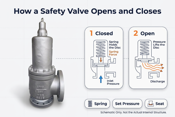
Under normal conditions, a spring presses the disc against the seat and keeps the process medium inside the system. When pressure at the inlet reaches the set value, the force under the disc overcomes the spring force. The disc lifts, and the medium flows out through the outlet.
As pressure falls, the spring pushes the disc back onto the seat. The valve closes and restores the pressure boundary. A ball valve or gate valve waits for an operator or actuator, while this device acts on pressure alone.
Several conditions shape this cycle:
The spring sets the resistance that holds the disc shut. Its configuration must match the intended set pressure and operating environment, because poor adjustment changes opening response and reseating.
Check spring material compatibility with the medium, resistance to corrosion and fatigue, correct adjustment of the compression mechanism, and stability across repeated pressure cycles. During maintenance, look closely at spring condition. Corrosion or fatigue changes the force on the disc, and the opening point can drift without any visible sign from outside.
An Industrial Safety Valve releases excess pressure when protected equipment nears or passes its specified limit. Typical locations include boilers, pressure vessels, steam systems, gas processing facilities, chemical lines, and utility systems. Each protected item has its own limits, so selection cannot treat every relief duty the same way.
| Valve Type | Operating Principle | Typical Use |
|---|---|---|
| Spring loaded | Spring force controls disc movement | Steam, gas, and liquid systems |
| Conventional | Direct spring-loaded mechanism | Controlled outlet backpressure |
| Balanced bellows | Bellows reduces backpressure influence | Variable outlet pressure |
| Pilot operated | Pilot controls the main valve | Specific pressure control needs |
Each option calls for a review of inlet pressure, outlet conditions, fluid properties, and installation. A conventional design suits systems with manageable backpressure. Changing discharge pressure may call for a balanced design, within the manufacturer's limits.
Inlet pressure sets the force on the disc. Outlet pressure can alter how internal parts move and how much differential is available for discharge.
When inlet pressure rises, the lifting force rises with it. Once that force beats the spring and other opposing forces, the valve opens. Outlet conditions still matter, since backpressure can influence opening pressure, discharge capacity, and reseating, depending on the design.
Engineers should examine normal operating pressure, relief set pressure, expected backpressure, pressure changes during operation, and losses in the inlet piping.
Backpressure is the pressure on the discharge side. It may come from a shared discharge header, downstream equipment, or friction in the outlet line. A common case is several valves venting into one flare header, where one valve's discharge raises the pressure seen by the others. Variable backpressure shifts the forces on the disc and changes opening and closing behavior. A balanced bellows design lessens that influence, but the allowed backpressure range must be confirmed in the manufacturer's data.
The disc and seat form the pressure boundary and control how the valve moves during relief. Geometry, surface condition, and material compatibility all affect sealing and stability.
When the valve opens, the disc creates a discharge passage. Unstable movement shows up as flutter or chatter, meaning repeated or irregular disc motion. It wears the seat, causes vibration, and reduces reliability. Likely causes include:
The seat must hold a seal while tolerating the temperature, pressure, and chemistry of the medium. Consider chemical compatibility, temperature resistance, corrosion and erosion resistance, wear from repeated operation, and leakage control needs. Metal-to-metal seating suits some high-temperature or demanding services, while other sealing arrangements fit where the design permits. Follow the manufacturer's application specifications.
A relief valve cannot be judged apart from its piping. Poor installation brings pressure loss, vibration, mechanical stress, or flow disturbance.
The line from vessel to valve should not cause excessive pressure loss, since that interferes with stable operation. Review pipe diameter and layout, length and fittings, losses during discharge, connection alignment, and vibration or mechanical loading. Follow engineering standards and installation requirements from the manufacturer.
The discharge line must account for flow, backpressure, temperature, and where the released medium goes. Steam and gas service needs attention to flow resistance and reaction loads on the pipe. Corrosive or hazardous media call for compatible materials, containment, and a safe discharge point.
| Condition | Possible Effect | Consideration |
|---|---|---|
| Large inlet pressure loss | Unstable operation | Review inlet resistance |
| High outlet backpressure | Changed opening behavior | Evaluate valve configuration |
| Pipe misalignment | Mechanical stress | Check alignment |
| Heavy vibration | Component fatigue | Review pipe supports |
| Corrosive discharge | Material degradation | Verify compatibility |
Safety valves work in steam headers, chemical units, and gas facilities, and the medium shapes material selection, discharge behavior, and upkeep.
High temperature can change spring characteristics, material strength, and sealing surfaces. Low temperature raises concerns about toughness and thermal contraction. Evaluate the full temperature range during normal operation and during relief. Thermal cycling deserves attention too, since repeated change contributes to fatigue and alters sealing.
Medium matters in practical ways:
Select body, spring, disc, seat, and connecting parts as one compatible assembly.
Automation is changing how maintenance teams track critical equipment. Safety valves remain mechanical devices, yet upstream and downstream pressure records can reveal changes in behavior when combined with proper inspection and testing. Useful signs include shifts in upstream pressure, variation in discharge pressure, abnormal fluctuation, unexpected buildup, and evidence of unstable operation.
Monitoring equipment does not replace the mechanical protection function. The valve must perform its duty independently of any non-safety system.
Maintenance should treat the valve as a complete assembly, not only its outer appearance. Inspect:
Follow applicable regulations, industry standards, and manufacturer recommendations for intervals and procedures.
Selection starts with the equipment and the conditions that create overpressure risk. Nominal pipe size and normal operating pressure alone miss important requirements.
| Application | Selection Factors |
|---|---|
| Steam systems | Temperature resistance, discharge capacity, seat performance |
| Gas processing | Set pressure, backpressure, sealing |
| Chemical plants | Corrosion resistance, fluid compatibility |
| Pressure vessels | Equipment limits, relief capacity |
| Utilities | Operating conditions, maintenance access |
Review applicable pressure equipment codes and local regulations as part of the engineering check.
A suitable supplier understands how construction, process conditions, and protection requirements connect. Comparing dimensions and connection types is not enough. Technical documentation, material information, configuration details, and application support all matter.
When discussing a Spring Loaded Safety Valve or any Industrial Safety Valve with our team, prepare:
These details give purchasing teams, engineers, and the supplier a shared technical basis. Contact our team to review valve configurations and request technical information for your project.